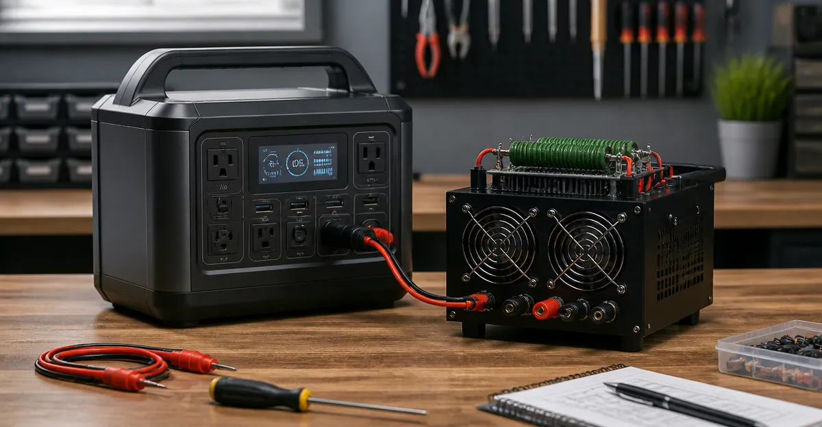
How to Build a Low-Cost Portable Power Station Load Bank: DIY Step‑by‑Step Guide for Safe, Budget‑Friendly Battery Testing
Introduction
Testing a portable power station requires a reliable load bank that can simulate real‑world demand without damaging the battery. This guide teaches the reader how to design and assemble a low‑cost load bank using readily available components. By following the instructions, one will gain a deeper understanding of battery performance, learn safe testing practices, and create a reusable tool for future projects. The approach balances affordability with professional results, making it suitable for hobbyists, field technicians, and small‑business owners.
The guide covers material selection, circuit construction, enclosure assembly, calibration, and safety verification. Throughout the process, recommended products are highlighted as optional tools that simplify each step. While the load bank can be built without purchasing any of the suggested items, the recommended power banks provide reliable voltage sources, built‑in safety features, and convenient form factors that reduce development time.
What You'll Need
- Portable power source(s) – see product recommendations below.
- Resistive load bank module (high‑wattage power resistors or a purpose‑built load bank kit).
- DC‑DC buck converter capable of handling the maximum current (e.g., 30 A, 12 V to 5 V).
- Heat‑sink and thermal paste for resistor cooling.
- Enclosure – a metal project box with ventilation.
- Wiring, connectors (Anderson Powerpole or barrel jacks), and a multimeter.
- Soldering iron, heat‑shrink tubing, and basic hand tools.
The following products from Amazon can serve as the portable power source and auxiliary tools. Each product is linked on first mention and includes price, rating, and key features that justify its selection.
Step 1: Define Load Requirements
Before purchasing any component, determine the voltage and current range you intend to test. Most consumer‑grade power stations output 12 V, 19 V, or 20 V and deliver up to 200 W of continuous power. For a low‑cost build, a target of 100 W at 12 V (approximately 8.3 A) provides a realistic workload while keeping resistor heat manageable.
Calculate the required resistance using Ohm's law: R = V² / P. For 12 V at 100 W, the resistance is 1.44 Ω. Selecting a set of 0.5 Ω, 1 Ω, and 2 Ω power resistors in parallel allows fine‑tuning of the load.
Document the desired load profile in a simple spreadsheet, noting the voltage, current, and power for each test point. This preparation ensures you purchase correctly rated resistors and avoids over‑loading the power source.
Step 2: Select a Portable Power Source
Choosing a high‑quality power bank simplifies the testing process because it provides built‑in protection circuits, LED status displays, and multiple output ports. The following products are suitable for different budget levels and power requirements.
- Zmmyuluo 10000mAh Power Bank – Priced at $18.99 with a 4.6/5 rating, this compact unit offers four built‑in cables, a digital LED display, and the ability to charge up to five devices simultaneously. Its 10 000 mAh capacity is ideal for low‑current load testing and fits easily in a pocket.
- JUOVI 20000mAh Power Bank – At $29.68 and a 4.4/5 rating, this model provides 45 W PD fast charging and four output ports, allowing you to test higher current scenarios without sacrificing portability.
- DaranEner Portable Power Station – For more demanding tests, this $71.98 unit delivers 200 W surge power, dual AC outlets, and a 89.6 Wh LiFePO4 battery. Its multiple ports and robust safety system make it suitable for load banks that exceed 150 W.
- UGREEN 25000mAh Power Bank – With a 4.5/5 rating and $79.99 price, this power bank supplies up to 165 W total output, including a 140 W single‑port charge. It is perfect for testing laptop‑class loads and offers built‑in dual USB‑C cables for cable management.
- AsperX 20000mAh Power Bank – Priced at $69.98 and rated 4.3/5, this device features a retractable USB‑C cable, a TFT display, and 165 W maximum output. Its aluminum unibody provides durability and efficient heat dissipation during prolonged testing.
Select the unit that matches the maximum power you intend to draw. For a 100 W load bank, the JUOVI or UGREEN models provide ample headroom, while the Zmmyuluo is sufficient for lower‑power verification.
Step 3: Build the Resistive Load Bank Circuit
Begin by arranging the chosen power resistors on a heat‑resistant board. Connect the resistors in parallel to achieve the target resistance. Use thick gauge wire (10 AWG or larger) to handle the expected current without excessive voltage drop.
Integrate a DC‑DC buck converter between the power bank output and the resistor network. The converter maintains a stable voltage as the load varies, ensuring accurate power measurements. Select a converter rated for at least 30 A to provide a safety margin.
Attach a high‑precision shunt resistor (0.01 Ω, 5 % tolerance) in series with the load to measure current via the multimeter. Connect the multimeter leads across the shunt to obtain real‑time current readings. Secure all connections with solder and heat‑shrink tubing to prevent accidental shorts.
Mount the resistors onto a metal heat‑sink using thermal paste. The heat‑sink should have fins spaced at least 5 mm apart to promote airflow. If the enclosure includes a fan, position it to blow air across the fins for active cooling.
Step 4: Assemble the Enclosure
Choose a metal project box that accommodates the heat‑sink, buck converter, and wiring while providing ventilation slots. Drill holes for the power input jack, output terminals, and a small fan if active cooling is desired.
Secure the buck converter and shunt resistor to the interior using standoffs. Route the wiring through cable glands to maintain the enclosure’s IP rating. Install a small digital voltmeter or LCD display on the front panel to show voltage and current at a glance.
Label each terminal clearly: "Input" for the power bank connection, "Load" for the resistor bank, and "Ground" for the common return. Proper labeling reduces the risk of reverse polarity, which can damage both the power source and the load bank.
Step 5: Test, Calibrate, and Verify Safety
Connect the selected power bank to the load bank input using the appropriate cable (USB‑C, barrel jack, or Anderson connector). Power on the bank and verify that the LED display shows the expected voltage.
Gradually increase the load by adding resistors in parallel or adjusting the buck converter setpoint. Record voltage, current, and calculated power at each step. Compare the measured values with theoretical calculations to confirm accuracy.
Perform a thermal check after each test interval. The resistors should not exceed 80 °C; if they do, improve airflow or reduce the load. Verify that the power bank’s built‑in over‑current protection engages if the current exceeds its rated limit.
Once the load bank operates reliably, document the calibration curve and store the device in a dry, temperature‑controlled environment. Regularly inspect the connectors for wear and replace any frayed wires.
Tips & Pro Tips
- Use a multimeter with a true‑RMS capability for accurate current measurement on non‑sinusoidal loads.
- When testing high‑capacity stations, stagger the load increase to avoid sudden inrush currents that could trigger protection circuits.
- Employ a fuse rated slightly above the maximum expected current (e.g., 10 A for a 100 W test) to provide an additional safety layer.
- Label each resistor with its resistance value and wattage rating; this simplifies future reconfiguration.
- If the power bank supports pass‑through charging, you can keep it connected to a wall adapter while testing, extending runtime and preventing deep discharge.
Troubleshooting
| Problem | Possible Cause | Solution |
|---|---|---|
| Voltage drops sharply when load is applied | Undersized wiring or excessive resistance in connectors | Replace with thicker gauge wire and ensure all connections are tight. |
| Power bank shuts off unexpectedly | Over‑current protection triggered | Reduce load or use a power bank with higher current rating such as the UGREEN 25000mAh Power Bank. |
| Resistors overheat quickly | Insufficient heat‑sink surface area | Add additional fins or a small 12 V fan to improve cooling. |
Conclusion
By following this guide, the reader has constructed a reliable, low‑cost portable power station load bank capable of safely testing a wide range of battery packs. The step‑by‑step approach emphasizes safety, accurate measurement, and modular design, allowing future upgrades as testing requirements evolve. Whether the user selects the budget‑friendly Zmmyuluo 10000mAh Power Bank or the high‑performance UGREEN 25000mAh Power Bank, the load bank will deliver consistent results and extend the lifespan of valuable portable power stations.
Continued use of the load bank will deepen understanding of battery health, discharge curves, and the impact of temperature on performance. The reader is encouraged to document test results, share findings with peers, and iterate on the design to suit emerging power technologies.
Products Mentioned in This Guide
Frequently Asked Questions
What is a load bank and why is it needed for testing portable power stations?
A load bank simulates real‑world power draw, allowing you to assess a battery’s performance and capacity without risking damage.
How much does it typically cost to build a low‑cost portable power station load bank?
Using common components, the build can be done for under $50, depending on parts you already have.
What basic components are required for the DIY load bank?
You need resistors or power‑rated heating elements, a heat sink, wiring, a switch, a voltage/current meter, and an enclosure.
How can I ensure safety while constructing and using the load bank?
Include proper fusing, secure connections, heat‑sink cooling, and never exceed the rated voltage or current of the components.
Can the load bank be calibrated for different battery capacities?
Yes, by adjusting the resistor values or using selectable taps, you can match the load to various battery sizes for accurate testing.