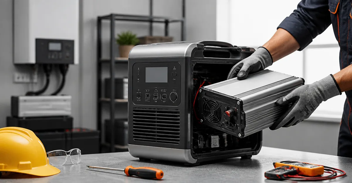
How to Replace the Inverter in a Portable Power Station: DIY Step-by-Step Safety Guide
Introduction
One of the most common failures in a portable power station is the inverter, the component that converts stored DC energy into usable AC power. Replacing a faulty inverter restores full functionality, allowing the device to power lights, laptops, and medical equipment once more. This guide will walk the reader through every phase of the replacement process, from safety preparation to final testing, while emphasizing best practices for personal protection and equipment longevity. By following these instructions, one can avoid costly professional repairs and gain a deeper understanding of the internal architecture of modern power stations.
What You’ll Need
- Precision screwdriver set (Phillips and Torx heads)
- Anti‑static wrist strap
- Multimeter capable of measuring DC voltage and continuity
- Soldering iron with fine tip (optional, for older models)
- Replacement inverter module compatible with the target power station
- Backup power source for testing – the LIBRIDS C600 portable power station is an excellent choice
Step 1: Ensure Personal Safety and Power Isolation
Before opening any electronic enclosure, one must eliminate the risk of electric shock. Disconnect the power station from all external loads and remove any attached solar panels or AC adapters. Press the power‑off button and allow the internal capacitors to discharge for at least five minutes. Attach an anti‑static wrist strap to a grounded metal surface to prevent static discharge that could damage sensitive components.
Step 2: Gather the Required Tools and Workspace
One should work on a clean, well‑lit surface free of conductive debris. Lay out the precision screwdriver set, multimeter, and any replacement hardware in an organized tray. Having a magnetic project mat can keep screws from rolling away. The LIBRIDS C600 can serve as a temporary power source for the multimeter, ensuring that the tester remains operational even if the main unit is offline.
Step 3: Remove the External Enclosure
Using the appropriate screwdriver, remove all screws securing the outer housing. Keep each screw in a labeled compartment to avoid confusion during reassembly. Gently lift the cover, taking care not to strain any internal cables that may be attached to the enclosure. If the unit features snap‑fit clips, apply even pressure with a plastic pry tool to prevent cracking the housing.
Step 4: Locate and Document the Existing Inverter
Inside the chassis, the inverter is typically a rectangular board with large heat sinks and multiple input and output connectors. Take a high‑resolution photograph of the board and its wiring layout before disconnecting anything; this visual reference will guide the reconnection process. Note the part number printed on the inverter; many manufacturers list compatible replacement part numbers in the service manual.
Step 5: Disconnect the Inverter Wiring
Using the precision screwdriver, loosen the terminal screws or release any locking tabs securing the DC input and AC output cables. Carefully pull the connectors straight out to avoid bending pins. At this stage, use a multimeter to verify that no residual voltage remains on the terminals before handling them further.
Step 6: Remove the Faulty Inverter Module
Most inverter modules are bolted to the chassis with small machine screws. Unscrew these fasteners and set them aside with the previously labeled screws. If the inverter is adhered with thermal pads, gently pry it away while preserving the heat‑sink surface for reuse with the new unit. Keep the heat‑sink in place; it will be re‑attached to the replacement inverter to maintain proper thermal management.
Step 7: Install the New Inverter
Place the new inverter onto the existing heat‑sink, ensuring that the thermal interface material (thermal pad or paste) covers the entire contact area. Secure the module with the original screws, tightening them to the manufacturer’s torque specification—typically 0.3 Nm for small electronics. Reconnect the DC input and AC output cables, making sure each connector clicks into place and that the polarity matches the documentation captured in Step 4.
Step 8: Verify Electrical Connections with a Multimeter
Before re‑closing the enclosure, power the unit using the LIBRIDS C600 as a temporary source. Measure the DC voltage at the inverter input to confirm it matches the specifications (usually 12 V, 24 V, or 48 V depending on the model). Then, set the multimeter to AC voltage mode and check the output terminals for the correct nominal voltage (typically 120 V or 230 V). If any reading is out of range, double‑check the wiring and connector seating.
Step 9: Reassemble the Power Station
Once electrical verification is successful, replace the outer housing and reinstall all screws in their original positions. Re‑attach any cable ties or fasteners that were removed during disassembly. Perform a final visual inspection to ensure no tools or loose parts remain inside the chassis.
Step 10: Perform a Full Functional Test
Connect a low‑power AC load such as a LED lamp or phone charger to one of the AC outlets. Power on the station and observe that the load operates smoothly without flickering. Gradually increase the load to the inverter’s rated continuous power (600 W for many mid‑range units) while monitoring the temperature of the heat‑sink. The built‑in 10 ms UPS of the LIBRIDS C600 can be used to simulate brief power interruptions and confirm that the new inverter responds correctly.
Tips & Pro Tips
- Always work in a well‑ventilated area; inverter modules can become hot during testing.
- Label each connector with a small piece of masking tape to avoid confusion during reassembly.
- If the original inverter failed due to overheating, consider upgrading to an inverter with higher efficiency; the PowerRaise technology in the LIBRIDS C600 demonstrates the benefits of advanced thermal design.
- Keep a spare set of machine screws; repeated removal can strip the threads in small aluminum chassis.
Troubleshooting
No AC Output Detected: Verify that the DC input voltage is present at the inverter. Check for loose connector pins or broken solder joints.
Excessive Heat on Inverter: Ensure the thermal pad is properly seated and that the heat‑sink is firmly attached. Consider adding a small external fan if ambient temperatures are high.
Intermittent Power Drops: Examine the battery management system for low‑state‑of‑charge protection; the power station may be limiting output to preserve battery health.
Conclusion
One has now learned how to safely replace a malfunctioning inverter in a portable power station, from initial safety measures to final performance verification. By following each step methodically and employing reliable tools such as the LIBRIDS C600 for backup power, one can extend the service life of the device and avoid unnecessary service fees. Mastery of this repair process also builds confidence for future maintenance tasks involving battery modules, charge controllers, and protective circuitry.
Products Mentioned in This Guide
Frequently Asked Questions
What safety gear should I wear when replacing a portable power station inverter?
Use an anti‑static wrist strap, safety glasses, and insulated gloves to prevent electric shock and static discharge.
Which tools are essential for the inverter replacement?
A precision screwdriver set (Phillips/Torx), a multimeter, and optionally a fine‑tip soldering iron for older models.
How do I verify that the replacement inverter is compatible?
Match the voltage, current rating, and connector type to the original unit’s specifications, often listed on the power station label or manual.
What is the proper way to test the power station after installing the new inverter?
Connect a low‑power AC load, measure output voltage with a multimeter, and ensure the device powers on without tripping safety circuits.
Can I replace the inverter myself without voiding the warranty?
Only if the manufacturer permits user service; otherwise, opening the unit may void the warranty, so check the warranty terms first.