How to Build a DIY Portable Battery Test Rig to Accurately Measure Capacity and Health
Introduction
This guide explains how one can create a portable battery test rig that delivers reliable capacity and health readings for lithium‑ion, LiPo, NiMH, and NiCd cells. The reader will learn how to select components, assemble a compact enclosure, and calibrate the system for repeatable results. Accurate measurement is valuable for hobbyists, drone operators, and anyone who relies on rechargeable batteries in critical applications. By following the steps, one will gain a deeper understanding of battery behavior and extend the service life of valuable power packs.
What You'll Need
- Portable enclosure (plastic project box, dimensions approx. 150 mm × 100 mm × 60 mm)
- Battery holder compatible with 2‑8 cell configurations
- Load resistor rated 5 Ω, 10 W (to discharge batteries at a controlled rate)
- SPST toggle switch for safe discharge control
- Connector wires (22‑AWG stranded, heat‑shrink tubing)
- Soldering iron and solder
- Multimeter for verification
- RCpow Cellmeter 8 – digital battery capacity checker and voltage tester
Step 1: Prepare the Enclosure
Begin by selecting a sturdy plastic project box that can accommodate the battery holder, the Cellmeter, and wiring without crowding. Drill mounting holes for the toggle switch on the side panel and for the Cellmeter display on the front panel, ensuring the LCD remains visible. Use a file to smooth any sharp edges around the holes to protect the user during operation. Secure the switch with a screw and verify that the opening aligns with the switch pins for a clean solder joint.
Step 2: Install the Battery Holder
Mount the battery holder inside the enclosure using self‑tapping screws, positioning it near the bottom to keep the center of gravity low. The holder must support up to eight cells in series, matching the Cellmeter's balance plug capability. Connect the holder's positive and negative terminals to short lengths of 22‑AWG wire, leaving enough slack to reach the switch and the Cellmeter. Apply heat‑shrink tubing over each solder joint to improve durability and prevent accidental short circuits.
Step 3: Wire the Load Resistor and Switch
Attach one lead of the 5 Ω, 10 W resistor to the positive terminal of the battery holder using a soldered splice. Connect the other lead of the resistor to one terminal of the toggle switch, creating a controlled discharge path. Wire the remaining switch terminal to the negative terminal of the battery holder, completing the circuit. This configuration allows the user to engage the load only when a capacity test is required, protecting the battery from unintended drain.
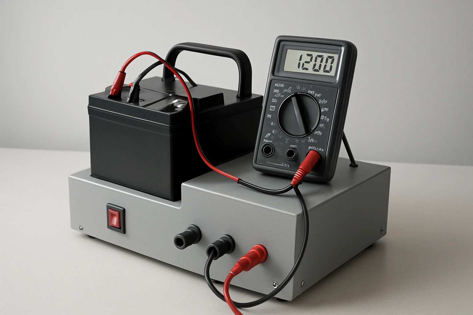
Step 4: Integrate the RCpow Cellmeter 8
Insert the RCpow Cellmeter 8 into the front panel opening, securing it with the supplied mounting clips. The Cellmeter provides a high‑visibility LCD display that shows individual cell voltages, total pack voltage, and capacity remaining during discharge. Its balance‑plug port accepts up to eight cells, enabling precise measurement of each cell's health without removing them from the holder. The device operates safely down to 1.2 V, preventing over‑discharge that could damage sensitive lithium cells.
Key specifications of the RCpow Cellmeter 8 include a 4.5‑star rating from 508 reviewers, a price of $11.69, and compatibility with LiPo, LiFe, Li‑Ion, NiMH, and NiCd chemistries. The one‑click measurement button simplifies data collection for users who are new to battery testing. By using this tool, one avoids the need for separate voltage meters and capacity analyzers, consolidating functionality into a single, affordable unit.
Step 5: Connect the Balance Plug
Attach the balance plug cable from the Cellmeter to the battery holder's balance connector, ensuring each cell pin aligns correctly. The Cellmeter will then read individual cell voltages and display the highest, lowest, and differential values on its screen. Verify the connection by powering on the Cellmeter and confirming that all eight cells appear with realistic voltage readings. If any cell shows an out‑of‑range value, double‑check the polarity of the holder connections.
Step 6: Calibrate the Test Rig
Before performing capacity measurements, calibrate the rig by fully charging a known‑capacity battery pack (for example, a 2200 mAh 3‑cell LiPo). Record the initial voltage and capacity reading displayed by the Cellmeter. Then engage the toggle switch to start the discharge through the resistor, allowing the Cellmeter to track capacity depletion in real time. When the pack reaches its cut‑off voltage (approximately 3.0 V per cell for LiPo), note the capacity value reported; this serves as the benchmark for future tests.
Step 7: Perform Capacity and Health Tests
To assess an unknown battery, fully charge it using an appropriate charger, then place it in the holder and connect the balance plug. Activate the discharge switch and monitor the Cellmeter's display; the device will show the decreasing capacity and highlight any cells that fall below safe voltage thresholds. After the test completes, compare the measured capacity to the manufacturer's rating to evaluate health. Repeat the procedure for each battery type you wish to evaluate, documenting results in a spreadsheet for long‑term tracking.
Tips & Pro Tips
- Always use a fire‑proof surface when discharging high‑capacity lithium packs, as rapid discharge can generate heat.
- Label each battery with its nominal capacity and chemistry to avoid confusion during testing.
- For more accurate capacity measurement, select a discharge current equal to 0.5 C (half the rated capacity) using an appropriately sized resistor.
- Periodically clean the balance plug contacts with isopropyl alcohol to maintain reliable voltage readings.
Troubleshooting
Problem: The Cellmeter displays erratic voltage readings.
Solution: Verify that the balance plug is fully seated and that no wires are loose. Check for corrosion on the contacts and re‑solder any questionable joints.
Problem: The discharge switch does not activate the load.
Solution: Measure continuity across the switch with a multimeter; replace the switch if it remains open when toggled.
Conclusion
By constructing this portable battery test rig, one gains the ability to measure capacity and health of a wide range of rechargeable cells with confidence. The integration of the RCpow Cellmeter 8 provides a cost‑effective, all‑in‑one solution that eliminates the need for multiple instruments. Regular testing helps prevent unexpected power loss, extends battery lifespan, and enhances safety for hobbyists and professionals alike. One is encouraged to refine the rig further, adding data logging or Bluetooth connectivity as experience grows.
Products Mentioned in This Guide
Frequently Asked Questions
What components are essential for a DIY portable battery test rig?
You need a small enclosure, a multi‑cell battery holder, a 5 Ω 10 W load resistor, a SPST toggle switch, 22‑AWG wire with heat‑shrink, a soldering iron, and a multimeter for verification.
How does the load resistor determine discharge rate?
The resistor’s resistance and power rating set a constant current (I=V/R), providing a controlled, repeatable discharge that reflects the battery’s capacity.
Can the rig test different battery chemistries?
Yes, it works with lithium‑ion, LiPo, NiMH, and NiCd cells as long as the voltage range and holder match the cells.
What safety precautions should I follow when discharging batteries?
Use the SPST switch to start/stop discharge, never exceed the resistor’s power rating, monitor temperature, and work in a well‑ventilated area away from flammable materials.
How do I calibrate the rig for accurate capacity measurements?
Measure the battery’s voltage before discharge, record the time until cutoff voltage using the multimeter, then calculate capacity (Ah = current × hours) and adjust your calculations accordingly.