How to Wire a Transfer Switch for a Portable Power Station: Safely Power Your Home
Introduction
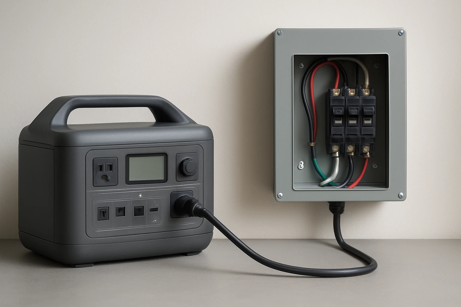
In the event of an outage, a portable power station can provide essential electricity, yet connecting it to a home circuit without proper equipment is hazardous. This guide explains how to wire a transfer switch so that the power station supplies selected circuits safely and automatically. The reader will learn required tools, step‑by‑step wiring procedures, and best‑practice tips that comply with the National Electrical Code. By following these instructions one can achieve reliable backup power while protecting equipment and occupants.
What You Will Need
- Manual transfer switch rated for at least 100 A and 24 kW (examples include the XMK 100A Manual Generator Transfer Switch, the Larrik 100A Generator Transfer Switch, or the MUJURUR 100A Generator Transfer Switch)
- Appropriate gauge wire (minimum 3 AWG copper for 100 A load)
- Wire connectors, grounding lug, and lockable terminal block
- Voltage tester, screwdriver set, and drill with appropriate bits
- Personal protective equipment (gloves, safety glasses)
- Optional remote control outlet kit such as the SURAIELEC Wireless Remote Outlet Kit for convenient on‑off control
Step 1: Plan the Circuits to Be Powered
Before any wiring begins one must decide which household circuits will receive backup power. Typical selections include refrigeration, heating, lighting, and critical medical equipment. One should draw a simple diagram showing the main breaker panel, the transfer switch, and the portable power station. Planning reduces the chance of overload and ensures that the transfer switch is sized correctly for the intended load.
Step 2: Shut Off Power and Verify Absence of Voltage
Turn off the main breaker in the service panel and lock it in the off position. Use a voltage tester to confirm that no voltage is present on the bus bars before touching any conductors. This safety step protects both the installer and the portable power station from accidental energization. Always follow lock‑out/tag‑out procedures prescribed by local regulations.
Step 3: Mount the Transfer Switch
Select a location near the main panel where the transfer switch can be securely mounted on a wall stud. The XMK 100A Manual Generator Transfer Switch features pre‑drilled holes and a corrosion‑resistant galvanized steel enclosure, making installation straightforward. Align the mounting holes, drill pilot holes, and secure the unit with the supplied screws. Ensure the NEMA 3R rating is respected by installing the unit in a dry, weather‑protected area if placed outdoors.
Step 4: Connect the Incoming Utility Feed
Run a pair of 3 AWG copper conductors from the main panel’s bus bars to the “Utility” terminals on the transfer switch. Tighten the terminal screws firmly to avoid loosened connections that could cause arcing. The XMK and Larrik models provide visible ON/OFF indicators that help verify proper connection. Attach a grounding wire to the dedicated grounding lug on the switch housing.
Step 5: Wire the Portable Power Station Output
Connect the output leads of the portable power station to the “Generator” terminals on the transfer switch using the same gauge wire as in the previous step. Many power stations provide a 120/240 V AC output with a dedicated plug; use an appropriate adapter or hard‑wire kit if required. The MUJURUR 100A Manual Transfer Switch includes a lock hole at the base to prevent accidental disengagement while the power station is feeding the house.
Step 6: Connect Load Circuits
Identify the breaker handles that will be controlled by the transfer switch. Typically one uses a double‑pole breaker that feeds a sub‑panel dedicated to essential loads. Run conductors from the “Load” terminals of the transfer switch to this sub‑panel. Ensure that neutral and ground conductors are bonded only at the main service panel, not within the transfer switch, to remain compliant with NEC requirements.
Step 7: Install a Remote Control Option (Optional)
For users who desire hands‑free operation, the SURAIELEC Wireless Remote Outlet Kit can be mounted near the transfer switch lever. The kit’s receiver plugs into a standard outlet and the transmitter can be placed anywhere within 100 ft, allowing the homeowner to toggle the switch without climbing onto the panel. This solution is especially useful for elderly occupants or for installations where the switch is located in a confined space.
Step 8: Test the Installation
After all connections are tightened, restore power to the main breaker while leaving the transfer switch in the “Utility” position. Verify that no circuits downstream of the switch are energized. Then engage the switch to the “Generator” position and start the portable power station. Use a multimeter to confirm that voltage appears on the load side and that the selected circuits receive power. Observe the indicator lights on the transfer switch to ensure proper operation.
Step 9: Secure and Label
Label each wire and terminal with durable tags that indicate “Utility,” “Generator,” and “Load.” Apply a lock to the transfer switch’s lockable hole to prevent unauthorized operation. Store the user manual in an accessible location and inform household members of the correct operating procedure. Proper labeling reduces confusion during future maintenance or emergency situations.
Tips & Pro Tips
- Always verify that the portable power station’s output capacity matches or exceeds the combined load of the selected circuits.
- Use copper conductors with a silver‑plated finish, as found in the XMK and MUJURUR models, to reduce resistance and heat buildup.
- Consider installing a surge protector downstream of the transfer switch to protect sensitive electronics.
- If the installation is performed in a region with strict code enforcement, consult a licensed electrician to obtain the necessary permits.
- Periodically test the system by simulating a power outage; this ensures that the switch and power station function as expected when a real outage occurs.
Troubleshooting
No Power on Load Side: Check that the transfer switch lever is fully in the “Generator” position and that the portable power station is turned on. Verify that all terminal screws are tight and that the grounding connection is secure.
Tripping Breaker: Reduce the number of circuits attached to the transfer switch or verify that the total load does not exceed 24 kW. Overloading is a common cause of nuisance trips.
Intermittent Switching: Inspect the wiring for loose connections or corrosion, especially in outdoor installations. Re‑tighten any suspect terminals and replace damaged conductors.
Conclusion
Wiring a transfer switch for a portable power station enables homeowners to maintain essential electricity during outages while adhering to safety standards. By selecting a robust 100 A switch, following the detailed wiring steps, and applying best‑practice tips, one can achieve a reliable backup system that protects both equipment and occupants. Regular testing and proper labeling will ensure long‑term performance and peace of mind.
Products Mentioned in This Guide
Frequently Asked Questions
What size transfer switch is required for a portable power station?
Use a manual transfer switch rated for at least 100 A and 24 kW to match most high‑capacity portable stations.
Can I connect a portable power station directly to my home wiring without a transfer switch?
No, direct connection is hazardous and violates the National Electrical Code; a transfer switch isolates the grid safely.
What basic tools are needed to wire a transfer switch?
You’ll need a screwdriver set, wire strippers, a voltage tester, appropriate gauge wire, and a torque wrench for terminal connections.
How do I select which circuits to power during an outage?
Identify essential loads (e.g., refrigerator, lights) and connect those circuits to the transfer switch’s designated output terminals.
Is a manual transfer switch safe for automatic backup power?
A manual switch requires you to flip it during an outage; for automatic backup you need an automatic transfer switch (ATS) designed for generator use.